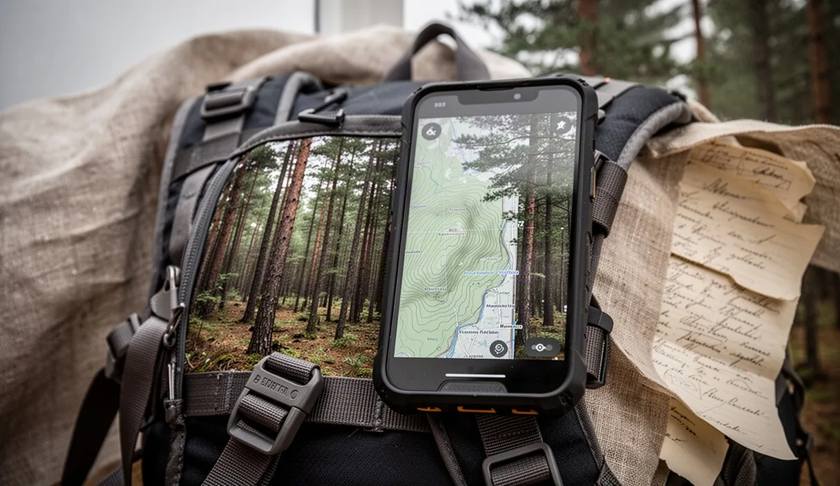
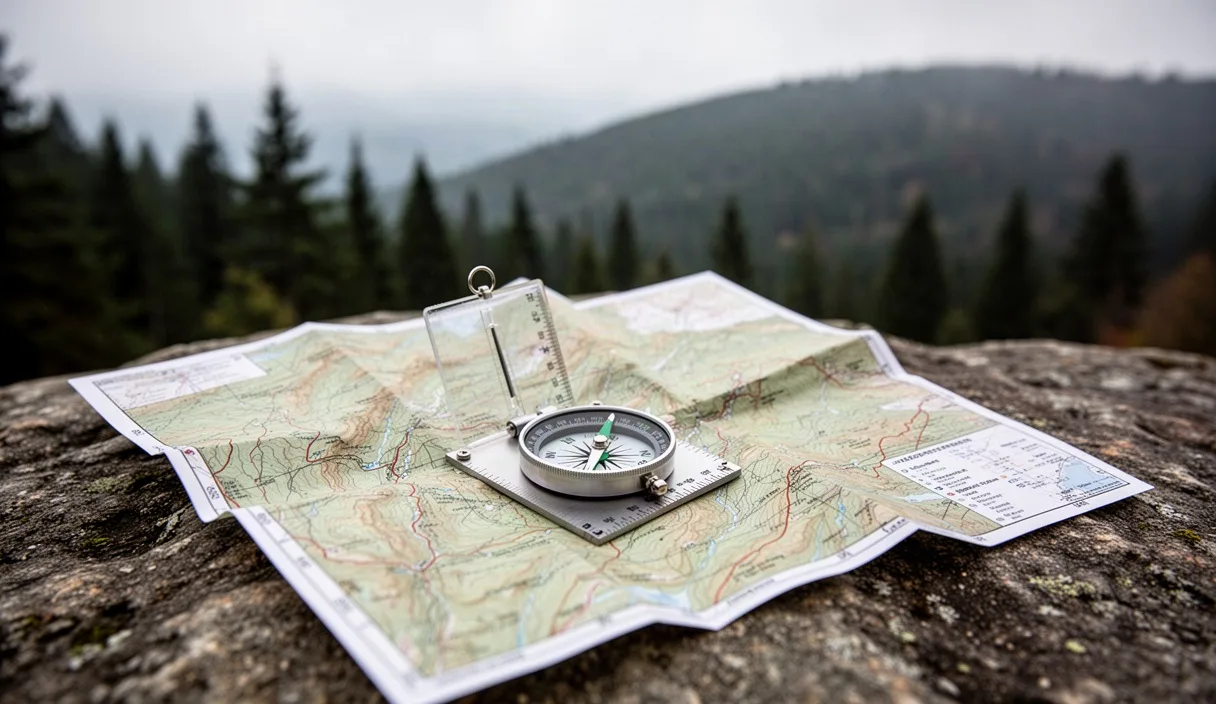
Paper maps do not run out of batteries. Electronics freeze, crack, take water damage, or lose satellite acquisition under dense hemlock canopies. A baseplate compass and a paper 1:24,000 scale topographic sheet weigh less than five ounces combined, operate across extreme temperatures, and provide spatial situational awareness that a two-inch digital screen cannot match.
Wilderness navigation requires matching real topography to two-dimensional ink lines while tracking direction across unknown terrain. Navigators who master fundamental map and compass skills do not rely on trail markings or guesswork. By learning to read land contours, calibrate for magnetic variance, shoot field bearings, calculate ground distance through foot pacing, and execute emergency recovery strategies, you gain the competence required to move safely off-grid.
Deciphering Contour Intervals, Index Lines, and Depressions
Contour lines connect points of equal elevation above sea level. When walking directly along a contour line, your elevation neither increases nor decreases. The vertical separation between each line is the contour interval, a fixed elevation value printed in the legend at the bottom margin of the map. On standard United States Geological Survey (USGS) 7.5-minute quadrangles, this interval is commonly 20 feet or 40 feet, though high-relief mountain maps may use 80-foot intervals and metric sheets frequently specify 10 or 20 meters.
Index contours appear every fifth line. These are rendered in heavier, darker brown ink and contain the specific elevation number printed directly within the line break. Read the numbers to determine whether the terrain rises or falls in a given direction. If you see index contours labeled 4400 and 4600 with four intermediate, lighter lines running between them, the difference is 200 feet divided by five spaces, confirming a 40-foot contour interval. Intermediate lines do not show numbers; determine their elevation by counting up or down from the nearest index line.
The spacing of contour lines shows terrain steepness. Closely packed lines indicate a steep slope, cliff, or headwall. Widely separated lines show flat valley floors, benches, or broad plains. Parallel lines that bend sharply into a V-shape point toward higher elevation; the bottom of that V marks a drainage, ravine, or stream bed where water runs down the crease. V-shapes or U-shapes pointing downhill indicate a ridge, spur, or rib pushing outward from the high ground.
| Terrain Feature | Contour Line Appearance | Field Identification |
|---|---|---|
| Spur / Ridge | U-shaped lines pointing toward lower numbers | Ground drops to your left, right, and front |
| Gully / Drainage | V-shaped lines pointing toward higher numbers | Ground rises to your left, right, and headwall |
| Saddle / Col | Hourglass gap between two concentric summit rings | Low dip between two higher topographic peaks |
| Cliff / Bluff | Lines merge into direct contact or overlap | Vertical rock face or sheer precipice |
| Depression | Closed rings with inward-pointing hatch marks | Sinkhole, dry kettle pond, or strip excavation |
Depression contours indicate low spots with no natural drainage outlet. Maps display these as closed loops with short hachure tick marks pointing inward toward the bottom of the basin. The first hachured depression contour matches the elevation of the adjacent regular contour line below it. Subsequent internal depression lines decrease by the map's established contour interval. Identifying depressions prevents confusing a deep sinkhole or dry tarn with a rounded hilltop.
Adjusting Your Baseplate Compass for Magnetic Declination
Navigational compass needles do not point to the geographic North Pole. They align with Earth's shifting magnetic field, pointing toward Magnetic North. Geographic North, also called True North, represents the northern rotational axis of the planet and serves as the vertical grid alignment on topographic maps. The angular difference between True North and Magnetic North is magnetic declination. Failing to adjust for declination causes drift, skewing a heading by hundreds of yards over a single mile.
Declination varies across the globe. In North America, the line of zero declination runs roughly from Lake Michigan down through the Gulf of Mexico. East of this line, magnetic needles pull west of True North, creating a westerly declination. In parts of Maine, declination reaches 15 degrees West. West of this zero line, the needle pulls east of True North. In Washington State, declination reaches 14 degrees East. Check the declination diagram in the lower margin of your map; note the date of publication, because magnetic poles shift over decades.
Quality baseplate compasses feature an adjustable declination scale controlled by a small brass screw or sliding key on the underside of the rotating bezel. Adjusting this scale ensures the internal orienting arrow compensates for the local angular variance:
- Locate the adjustment mechanism: Turn the compass over to access the adjustment screw or gear track on the clear housing.
- Insert the adjustment tool: Use the small metal key attached to the compass lanyard, or a precision screwdriver tip, into the slotted brass screw.
- Rotate the orienting arrow: For an East declination of 12 degrees, rotate the internal orienting arrow 12 degrees to the East marker on the internal degree ring. For a West declination, turn it toward the West marker.
- Confirm the alignment: Check that the primary degree ring still aligns with the travel line while the underlying orienting shed reflects the offset angle.
If using an entry-level compass without an adjustable gear, perform manual arithmetic for every bearing. When moving from a map bearing to a field heading in an area with West declination, add the declination value: Map Bearing + West Declination = Field Bearing. For East declination, subtract the value: Map Bearing - East Declination = Field Bearing. When transferring a field bearing taken from a sighting onto a paper map, reverse the math. Forgetting whether to add or subtract is the most common mathematical mistake in wilderness travel; purchasing an adjustable compass eliminates this manual step.
Taking a Field Bearing to Visible Distant Landmarks
A bearing is an angle measured clockwise from North, expressed in degrees from 0 to 360. Taking a bearing translates a line of sight to a physical feature into a concrete numerical direction. This measurement allows you to identify unnamed summits, maintain a straight line through heavy timber, or plot a location fix on paper.
Aim the Compass at the Target
Hold the baseplate flat against your stomach at waist height, or hold a sighting compass up to eye level. Point the baseplate direction-of-travel arrow directly at the distant landmark, such as an isolated peak, a fire lookout, or an alpine notch. Keep your body aligned with the compass baseplate; turn your entire torso rather than swiveling the compass in your hands.
Align the Housing
Turn the rotating dial housing until the outlined orienting arrow on the clear floor lines up with the magnetized red needle. Outdoor instructors describe this as putting "red in the shed." Ignore the white or black south-pointing end of the needle. Verify that the baseplate remains aimed dead-center on the target while you complete this alignment.
Read the Azimuth Value
Read the exact degree number located directly at the index line at the top of the dial, immediately below the direction-of-travel arrow. This number represents your magnetic field bearing to the objective. If your compass declination has been adjusted, this number is also your True North bearing.
Plot the Position Line with Resection
Pinpoint your current location on the map using triangulation, known in field navigation as resection. Choose two, or preferably three, distinct visual landmarks that sit between 60 and 120 degrees apart from one another:
- Shoot the field bearing to the first recognizable landmark following the actions detailed above.
- Place your compass on the map. Align one edge of the baseplate with that same landmark's symbol on the sheet.
- Rotate the entire baseplate around that landmark point until the orienting lines on the dial floor align parallel to the map's north-south grid lines.
- Draw a thin pencil line across the map along the straight edge, extending back toward your general area.
- Repeat the measurement and plotting sequence for the second and third landmarks.
The pencil lines will cross. If three landmarks were used, they will form a small triangle. If the field bearings and manual drawing were precise, your position sits inside that triangle. A small triangle measuring less than one-tenth of an inch across indicates accurate field sightings.
Pace Counting: Measuring Traveled Distance on Foot
Navigation fails if you know your travel direction but cannot measure how far you have walked along that vector. In thick fog, open snowfields, or heavy lodgepole pine timber where landmarks vanish, pace counting provides the most reliable way to monitor linear ground travel. A pace equals one double-step, counted each time your non-dominant or designated lead foot strikes the soil.
Establish a baseline pace count on a measured 100-meter flat course laid out with a surveyor tape. Walk the course four times at a standard, unhurried trail stride. Count each double-step: left foot down, right foot down (count one); left foot down, right foot down (count two). Record the number of paces for each pass and calculate the average. For an average adult, this baseline typically ranges between 58 and 66 paces per 100 meters.
Terrain factors distort your flat baseline count. You must adjust your pace estimates based on conditions:
- Steep ascents: Strides shorten naturally. Paces per 100 meters increase by 12 to 20 paces above your flat baseline.
- Steep descents: Stride lengths become erratic. Paces may decrease as you step long, or increase if braking through loose talus.
- Heavy mud, snow, or scree: Foot slippage causes wasted motion. Add 8 to 15 paces per 100 meters to compensate for poor traction.
- Pack weight: A 40-pound backpack shortens hip extension. Expect an increase of 4 to 8 paces per 100 meters on moderate grades.
Track your accumulated distance using mechanical pace beads, also known as ranger beads. Thread a cord with thirteen beads separated by an overhand knot into two sections: nine beads in the bottom section and four beads in the top section. Each time you reach your calculated 100-meter pace count, pull one bottom bead down. When all nine lower beads are down and you complete the tenth 100-meter stretch, slide all nine lower beads back up and pull down one upper bead to mark one completed kilometer. Four upper beads allow you to track up to five total kilometers before resetting the line.
Recovering Known Position After Losing the Main Trail
Losing a maintained trail requires deliberate, methodical action. The moment tread disappears and blazes vanish, execute the classic recovery protocol: Stop, Think, Observe, Plan. Continued walking while anxious creates compound errors, taking you deeper into drainages or away from trail corridors. Sit down, drink water, and check the time. Remaining motionless lowers the pulse and halts the impulse to push forward blindly.
Do not cast about in random circles. Mark your current position physically by tying bright survey tape to a branch at eye level, piling three distinct rocks, or driving your trekking pole into the ground. This marks your zero point. If exploratory short walks fail to relocate the path, you must be able to return to this exact spot without ambiguity.
Use the aiming off technique when navigating to a linear catching feature. If you know a gravel logging road or a hiking trail lies 400 meters north of your lost position, do not shoot a bearing intended to hit the trail-road junction dead-on. Field error, bush avoidance, and compass drift almost always introduce a three to five-degree error. If you strike the road and see nothing, you will not know whether the junction lies to your left or to your right.
Instead, intentionally calculate a bearing aimed 200 meters to the left (west) of the junction. When you reach the road, you know with mathematical certainty that the targeted junction sits to your east. Turn right along the road and proceed directly to your checkpoint. This technique works with rivers, distinct ridge systems, transmission line cuts, and established trails.
Employ back azimuths to retreat safely. If you advanced along a bearing of 042 degrees from a known saddle before losing the route, reverse your travel line. To calculate a back azimuth, add 180 degrees to bearings under 180, or subtract 180 degrees from bearings over 180. For a heading of 042 degrees, 42 + 180 = 222 degrees. Dial 222 degrees onto your index line, align the needle inside the orienting housing, and walk that back bearing straight back to the known saddle.
Common Mistakes
Even basic navigation falls apart when fundamental procedures are skipped or executed carelessly. Avoid these frequent field errors:
- Local magnetic interference: Holding the compass close to metal items deflects the needle. Maintain at least three feet of clearance from steel pack frames, ice axes, bear spray canisters, folding knives, and smartphones. Keep at least ten feet away from wire fences and twenty yards away from motor vehicles or power lines.
- Reading the needle in reverse: Putting the white or black south-pointing needle into the orienting shed instead of the red north needle throws your route off by 180 degrees. Always confirm the red needle points into the red housing bracket.
- Ignoring map scale units: Measuring distances using an inch ruler on a map printed in a 1:50,000 metric scale creates enormous calculation errors. Always verify that your baseplate ruler matches the scale printed in the map marginalia.
- Forgetting terrain relief in distance estimates: Topographic maps display horizontal planimetric distance, not true ground surface distance. Climbing up a 35-degree mountain slope requires more steps and time than the flat horizontal map distance indicates.
- Failing to sight intermediate waypoints: Looking down at the compass while walking causes drift around rocks and trees. Instead, shoot your bearing, spot a distinct dead tree, boulder, or unusual shrub along that line of sight, walk to it, and then repeat the sighting process.
Practical Next Steps
Do not test these skills for the first time during an alpine storm or deep in backcountry terrain. Take a local 1:24,000 USGS topographic quadrangle to a regional county park or a state forest featuring established trails and clear landmarks. Measure out a 100-meter baseline along a flat path, calculate your personal pace count, and craft or purchase a set of pace beads to practice recording intervals.
Practice shooting bearings to water towers, trail intersections, and hilltop structures. Plot those lines on your map to confirm your plotted intersection matches where you stand on the path. Seek out a local orienteering club to practice navigating through unfamiliar terrain under low-consequence conditions. For high-angle alpine travel, winter snowpack travel, or technical mountaineering, seek formal field instruction from certified mountain guides or accredited outdoor education institutions.